
....looking at some of the lesser known aspects |
During the early days of aviation aircraft construction was not so much an industry as an art. It took real skill to create the forms for an airplane, and such were not quickly gained by standardized industrial training. The companies which built most of the WW I machines were not formed for that purpose, and their industrial experience was in other areas. Some built railroad rolling stock, others built automobiles, while some built industrial machinery. However, many of the aircraft designers had studied flight engineering, though some confessed that they designed their planes more by eye and feel. It must be remembered that many pilots climbed into a light and rickety machine simply on the word of the designer that the plane would indeed fly. When WW I started the aircraft industry was only ten years old, and the pilots and designers were true innovators and creators. Few of us today can appreciate how much nerve and courage it really took to plunge ahead in this field. Many design concepts were still bewildering to designers, such as wing flutter (the sudden vibration of the wings caused by turbulence) which could often tear a wing free. Pilots could also find the fabric suddenly shed from a wing in a dive, and sometimes a plane would literally fall apart in mid-air for no conceivable reason (the French pilot des Moulinais died in such a manner). As the war progressed engine power increased tremendously, and the trend was toward larger and heavier machines. In just four years the British went from the light de Havilland DH-2 to the large, heavy and powerful Sopwith Snipe. Indeed, necessity is the mother of invention. |
Aircraft Design and Construction.......... |
Basic Aircraft Layout |
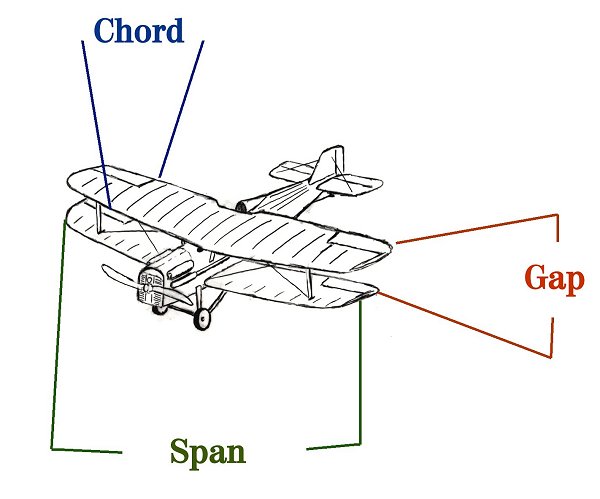
While most are familiar with the basic layout of an airplane, there are some aspects which are lesser known. Chord: an arbritrary line stretched from the leading edge to the trailing edge of a wing. It is usually measured as the point farthest apart, although a wing can be considered to have more than one chord measurement. Chord impacts lift..... the longer the chord typically the better lift. However, greater chord can also induce more drag. Gap: the distance between the two wing surfaces, typically measured perpendicular from one chord line to the other. Gap can impact turbulence and lift if too narrow. |
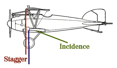
A few other items unfamiliar to many is that of Stagger and Incidence. Stagger: simply put, stagger is measured from the leading edges of the wings, using a plumb line. If the upper wing is ahead of the lower, then the stagger is positive. If the lower wing is ahead of the upper (such as on the DH-5 and Sopwith Dolphin) then the stagger is negative. Adjusting the stagger can improve pilot vision, but it also changes the wing's position in the plane's center of gravity (which can have serious consequences). Even 1/4 of an inch change could cause the machine to be excessively nose or tail heavy and impact longitudinal stability. Incidence: this is the amount of up angle a wing has in relation to the line of thrust. In some WW I machines, the tail plane's incidence could be manually adjusted by the pilot. Incidence aides in lift, but too much causes turbulence over the wing surface, thereby reducing lift. It was also important for ground crews to make sure the incidence was the same on both sides. If usage altered one side, then the plane may fly wing-down on one side and degrade performance. |
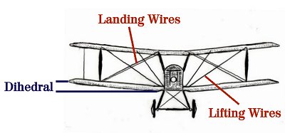
Although most know that the wires on a plane's wings were to add strength, few realize that sets of wires have a different purpose. The wire layout on aircraft could present real difficulties for ground maintenance crews. For example, the Pfalz D.XII required constant tightening of the wires, and had many to tighten as well. Landing wires were used to add strength to the wings when the plane was on the ground, while lifting wires provided such while the plane was flying. The wings of these aircraft were designed to flex considerably, and the wires would loosen during extended flight (called elongation). Ground crews therefore had to constantly check them, as well as ensure that tightening of the wires did not warp the wing shape. Furthermore, it was crucial to make sure that all of the wires on the wing were of the same tension. Wings were often checked with levels to maintain the proper dihedral and incidence, although weighted string was often used. Improper wire tension could adversely impact both of these. Aircraft wing structure could be either of single-bay or two-bay layout. A single bay layout had only one set of wing struts per side (such as on the Se-5a above). The two-bay layout involved two sets of struts per side (such as the Spad XIII). The two-bay layout involved more maintenance, since there were more struts and wires to inspect. As to the struts, it was essential that they be inspected for warping and cracking. While in flight, lifting forces placed the struts in compression. If weakened in any way they could fail without warning with often fatal results. Moreover, bent or warped struts created excessive turbulence and degraded performance. The dihedral of the wings varied from plane to plane, but the basic idea was for this to provide stability to the machine. The greater the dihedral (to a certain limit of course), the more self-righting capability the plane has. If the dihedral was not correct it could cause the propellor to not pull from the true center of resistance, and the plane would drift slightly sideways. Therefore, ground crews carefully checked dihedral on a regular basis to keep the angle consistent and accurate. |